
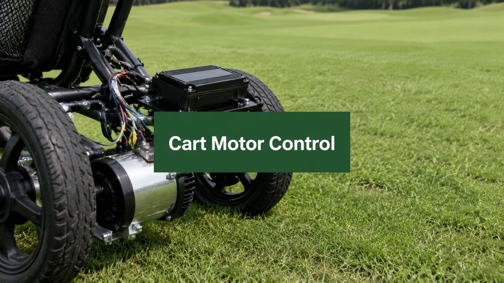
You're halfway up a fairway when the slope steepens, the cart starts to lag behind, and your thumb has to choose between more power and a controlled stop. On a narrow path, the problem gets harder. A delayed reverse command, a weak battery, or a remote that loses its signal can turn a convenient motorized push cart into something you have to chase.
Learning how to control a motor for this use case means more than connecting a battery and pressing a button. The motor, controller, wiring, remote, battery, braking system, and mechanical frame must work as one system. The setup also has to tolerate grass clippings, moisture, vibration, uneven ground, and repeated stop-start maneuvers throughout a round.
What Motor Control Actually Means on a Push Cart
On a golf push cart, motor control is the coordinated work of a motor, electronic speed controller, battery, and command device. The motor creates torque at the wheel. The battery provides electrical energy. The electronic speed controller, or ESC, interprets the remote's commands and meters current into the motor. The handheld remote turns button presses or wheel movements into forward, reverse, speed, and brake signals.
That combination matters because each component has a different job. A strong motor can't compensate for a controller that overheats on a hill. A capable ESC can't deliver consistent torque if the battery voltage collapses under load. A carefully chosen motor still performs poorly when the wiring is too small, connectors are loose, or the wheel loses traction.
Practical rule: Treat the cart as a complete drive system, not as a motor with accessories attached.
The basic control loop is easy to visualize. You press forward, the receiver passes that command to the ESC, and the ESC applies controlled electrical power to the motor. When you reduce speed, the ESC reduces the motor's effective drive. When you brake, it changes the electrical state of the motor to slow the wheel, while the cart's mechanical brake provides physical restraint where needed.

Modern motor control developed from early DC motor systems in the 19th century to electronic drives in the 20th century. Hans Christian Oersted's discovery in 1820, Michael Faraday's primitive DC motor in 1821, Thomas Davenport's practical commutator motor in 1832, and the first electric-motor patent in 1837 helped establish the foundation. The Ward Leonard drive system in 1891 became an important method for DC speed control, while electronic inverters later made continuous AC speed control practical. By the 1980s, AC vector control had largely displaced older DC approaches where precision, response, and speed range mattered. This history explains why a compact cart can now vary speed, reverse, and brake without bulky mechanical controls. The historical development is outlined in this review of motor-control evolution.
A practical build also needs a clean project plan. If the cart is part of a tournament setup, coordinating equipment, participants, and course logistics through find golf event planning help can keep the technical work from becoming an afterthought.
PWM Speed Control for Smooth Variable Speed
A motorized cart needs variable power, not a crude on/off switch. Full battery power makes the wheel respond sharply, while removing power makes it coast or stop. That behavior is difficult to manage beside a bunker, on wet grass, or near another golfer.
Pulse-width modulation, or PWM, solves this by switching the motor supply rapidly. The controller keeps the switching frequency fixed and changes the proportion of each cycle spent switched on. That proportion is the duty cycle. A lower duty cycle produces gentler average drive, while a higher duty cycle provides more torque and speed, subject to the motor, battery, controller, and load.
The principle is simple:
- Low duty cycle: The motor receives shorter power pulses and the cart moves more gently.
- Higher duty cycle: The pulses stay on longer, producing stronger drive for acceleration or climbing.
- Changing duty cycle: The controller adjusts wheel speed without repeatedly applying and removing full mechanical drive.
The actual frequency needs careful selection. Expert guidance for BLDC control recommends a PWM frequency at or above 50 kHz to reduce audible noise and current ripple, with 80 kHz or more preferred for motors with very small electrical time constants. That guidance comes from Portescap's explanation of PWM in brushless DC motor control, so I wouldn't assume that a lower frequency is automatically suitable for a small cart motor. Excessive ripple and heating can appear when PWM is too low or motor inductance is too small. External inductance can slow current rise and fall, but the controller still needs to be configured correctly.

A remote thumb wheel or speed button usually changes a command value rather than directly changing motor voltage. The ESC converts that command into a PWM duty cycle through its throttle curve. A good curve gives the cart a predictable walking response near the bottom of the control range and reserves stronger output for slopes.
Smooth ramping matters just as much as the duty cycle itself. If the controller jumps instantly from low output to high output, the gearbox, belt, tire, and wheel mount absorb a sharp shock. A programmed acceleration ramp makes the cart feel calmer and reduces traction loss. Current limiting adds another layer of protection when the wheel meets wet grass, a curb, or a steep approach.
For broader maintenance principles, the maintenance strategy for process industry drives offers useful context on treating drives as systems that need inspection and configuration, not as sealed components that can be ignored. For a golf-specific overview, see this guide to electric golf cart speed control.
Forward, Reverse, and Braking Through the Remote
A forward command begins at the handheld remote. The remote transmits a coded radio signal to a paired receiver, and the receiver passes that instruction to the ESC. In a brushless system, the ESC then energizes the three motor phases in a sequence that produces rotation in the desired direction.
Forward rotation is the direction that drives the cart along its normal rolling path. Reverse rotation changes the phase sequence so the magnetic field turns the rotor the other way. With a brushed DC motor, the same result comes from reversing the polarity across the motor terminals, usually through an H-bridge or reversing contactor.
Braking depends on the controller design. The ESC can use regenerative braking, sending some motor-generated energy back toward the battery, or it can use electrical braking by creating a controlled current path through the phases. Neither method replaces a physical parking brake. On a downhill slope, the motor brake slows the wheel, but the mechanical brake holds the cart when you step away.
On a slope: Release drive before selecting reverse, let the cart settle, and use the hand or parking brake when the cart must hold position.
Never reverse a moving cart abruptly. The sudden change in torque travels through the gearbox, wheel hub, tire contact patch, and mounting bracket. A controller with a release-then-press sequence, deliberate reverse confirmation, or a double-press requirement is safer than one that changes direction from a single accidental button press.
Remote response also matters on narrow paths. Even a short delay can change where the cart is when the command takes effect, so keep the cart at a speed that leaves room for stopping. If the system begins to feel unpredictable, return to manual control rather than compensating with sharper button inputs. This explanation of electric motor remote control provides a golf-cart-focused view of the command interface.
Sensorless brushless systems add another layer. The controller can monitor zero-crossing back-EMF on the unpowered winding, process that signal, and then commutate the next phase. A startup sequence or Hall sensors often helps the controller establish rotor position before handing control to sensorless operation. The vendor reference design for six-step sensorless BLDC control also highlights a practical issue, PWM placement must leave enough off-time for reliable back-EMF sampling.
Wiring, Pairing, and Sizing the Controller to the Motor
Start on the bench, not on the cart frame. Read the motor voltage and current information, identify the battery's output, and confirm that the ESC supports the motor type. Brushless motors need a compatible three-phase controller, while brushed motors need a controller designed for their commutation method.
Sizing should account for hills and acceleration. The controller's continuous current capability needs to suit the motor's normal draw and the expected load surges. Don't rely on a controller that barely matches the motor's label, because a wheel climbing a slope can demand more current than it uses on level ground. Motor and drive compatibility also affects performance, and Schneider Electric's motor and drive FAQ explains why mismatches can require different control modes and overload settings.
A typical bench workflow looks like this:
- Protect the battery lead. Install the battery connection with an appropriate in-line fuse and keep polarity clear.
- Add the main power control. Use a key switch or push-button so the controller can't remain energized accidentally.
- Connect the command path. Route the receiver, throttle, or remote signal cable away from high-current phase wires.
- Attach the motor conductors. A brushless motor normally uses three phase wires and may also have Hall sensor leads.
- Check every connector. Tug lightly on crimped terminals and inspect for exposed copper, looseness, or crushed insulation.

Pairing normally requires putting the receiver into bind mode, switching on the remote, and confirming that the receiver stores that handset's identity. Direction settings may sit behind small DIP switches or inside an app menu. Test those settings with the wheel raised safely off the ground. Confirm forward, reverse, brake, and throttle release before securing the motorized wheel to the frame.
A 15-second no-load spin can expose reversed phase order, rough bearings, sensor faults, or an incorrect throttle endpoint. It won't prove the cart is ready for a hill, but it catches wiring mistakes before the tire contacts the ground.
For a more general sizing perspective, the discussion of sizing motors for hydraulic systems reinforces the same engineering habit, match the motor, drive, supply, and working load rather than choosing one component in isolation.
Remote Driving Limits and Safer Operating Habits
Remote operation works best when the cart stays close, visible, and easy to stop. Manufacturer guidance commonly gives remote-controlled golf trolleys a hard operating limit of about 50 meters, while advising users to keep the trolley around 25 meters away with a clear line of sight because hills, trees, interference, and hidden hazards reduce safe control distance. The operating guidance also recommends switching to manual mode in car parks, on steep descents, and in crowded areas, as described in this remote trolley operating manual.
Those figures aren't a target for normal play. A cart near the edge of a fairway may disappear behind a rise before it reaches the stated limit. Tree canopy, clubhouse equipment, parked carts, and other people can interrupt the path between transmitter and receiver. Keep the cart where you can see its wheels, not merely the top of its handle.
Remote driving also changes the mechanical behavior of the trolley. In remote mode, the motors try to maintain straight, continuous movement. If you push or steer manually while that mode remains active, the system can counteract your input until you return to manual control, according to the PowaKaddy remote manual.
Uneven ground demands more caution than a flat fairway. Independent trolley guidance warns that remote driving can make a trolley more likely to tip on uneven or uphill terrain because the operator isn't physically stabilizing it. One manual notes that the center of gravity shifts slightly outside the stable range while climbing and recommends hand steering on rough ground, as set out in the TiCad radio-module manual_UserManual_TiCad%20Funkmodul%20Set.pdf).
Before releasing the cart, check:
- Visibility: You can see the complete route and the stopping area.
- Slope: Manual mode is ready for a steep descent or side slope.
- Distance: The cart remains comfortably inside the clear-view operating range.
- Stop confirmation: The wheels have stopped before you walk toward the cart or retrieve a ball.
Common Motor Control Problems and How to Fix Them
Most field failures fall into a few recognizable patterns. Diagnose the symptom first, then test the power path before replacing expensive parts.
If the cart gives no response, check the main switch, fuse, battery charge, receiver binding, and remote battery. Use a multimeter to verify battery voltage at the pack and again at the controller input while the system is switched on. A large difference between those points indicates a fuse, connector, switch, or cable problem rather than a failed motor.
When the cart runs but stutters under load, inspect phase connectors for corrosion and heat discoloration. Check whether the battery voltage falls sharply during acceleration, and look for a controller that shuts down after a steep climb because of temperature protection. A motor that spins smoothly with the wheel lifted but cuts out on grass usually points toward supply, current, thermal, or connection trouble.
| Symptom | Likely Cause | Fast Fix |
|---|---|---|
| No response | Discharged battery, open fuse, dead switch, or unbound remote | Test voltage through the complete power path, then bind the remote again |
| Stutter under load | Corroded connector, weak battery, poor phase connection, or thermal shutdown | Clean and tighten connectors, test loaded voltage, and allow the controller to cool |
| One direction only | Faulty reverse relay, direction switch, or endpoint setting | Check the handset command, inspect the reversing circuit, and reset endpoints |
| Weak braking | Incorrect brake setting, phase issue, or Hall-sensor fault | Confirm controller configuration and inspect sensor wiring |
| Motor hums but doesn't turn | Wrong phase order, failed Hall signal, or controller commutation fault | Test phase continuity and sensor output before changing the motor |
A controller swap often makes more sense than a motor replacement when the motor has clean bearings, consistent winding resistance, and no visible overheating. Conversely, a controller won't cure a motor with damaged insulation, seized bearings, or a mechanically loose gearbox.
Use the multimeter with the wheel safely isolated. Don't short phase wires together, and don't probe moving parts with loose leads. This guide to testing a golf cart motor can help organize the basic checks.
Putting It All Together on the Course
A reliable round starts before the first tee. Check the remote, battery connection, receiver response, wheel attachment, and parking brake while the cart is stationary. A quick no-load response check confirms that forward, reverse, and braking commands still behave as expected after transport.
Leaving the clubhouse calls for a conservative PWM ramp. Start slowly, let the wheel establish traction, and increase speed only after the cart tracks straight. On a level path, steady mid-throttle cruising is easier on the drive system than repeated bursts. Near a steep approach, increase drive progressively rather than stabbing the throttle and forcing the tire to break traction.
Tight par-3 walkways, wet side slopes, crowds, and blind rises are good places to use manual control. The remote is useful when you need controlled movement without holding the cart, but it can't replace your judgment about terrain or visibility. If a signal drops mid-round, release the command, approach the cart safely, and restore manual control instead of repeatedly pressing buttons from a distance.
At the turn, inspect the battery connection and note whether the cart has lost its normal response. A battery that feels fine on level ground may show weakness when the back nine includes longer climbs. Keep the handset in a clipped pouch, protect it from moisture, avoid sharp throttle bursts on wet grass, and park with the mechanical brake engaged rather than relying only on electronic hold.
The practical lesson is simple. Reliable motor control comes from repeatable routines, correct sizing, clean wiring, sensible PWM behavior, and knowing when the remote isn't the right tool for the terrain. Those habits protect the motor, controller, battery, and cart frame far more effectively than a single upgrade.
Caddie Wheel offers a drop-on motorized wheel with a snap-in bracket, variable-speed handheld remote control, forward and reverse operation, and braking for compatible three- and four-wheel push carts. Visit Caddie Wheel to review the setup and see whether its power-assist approach fits your hills, paths, and walking routine.
Share:
Drift Golf Cart Guide: Designs, Legality, and Smarter
3 Wheel Motorized Cart Guide for Golfers in 2026